
Edge Gateway with Digital Inputs and Relays: Selection Guide for Local Alarms and Control Handoffs
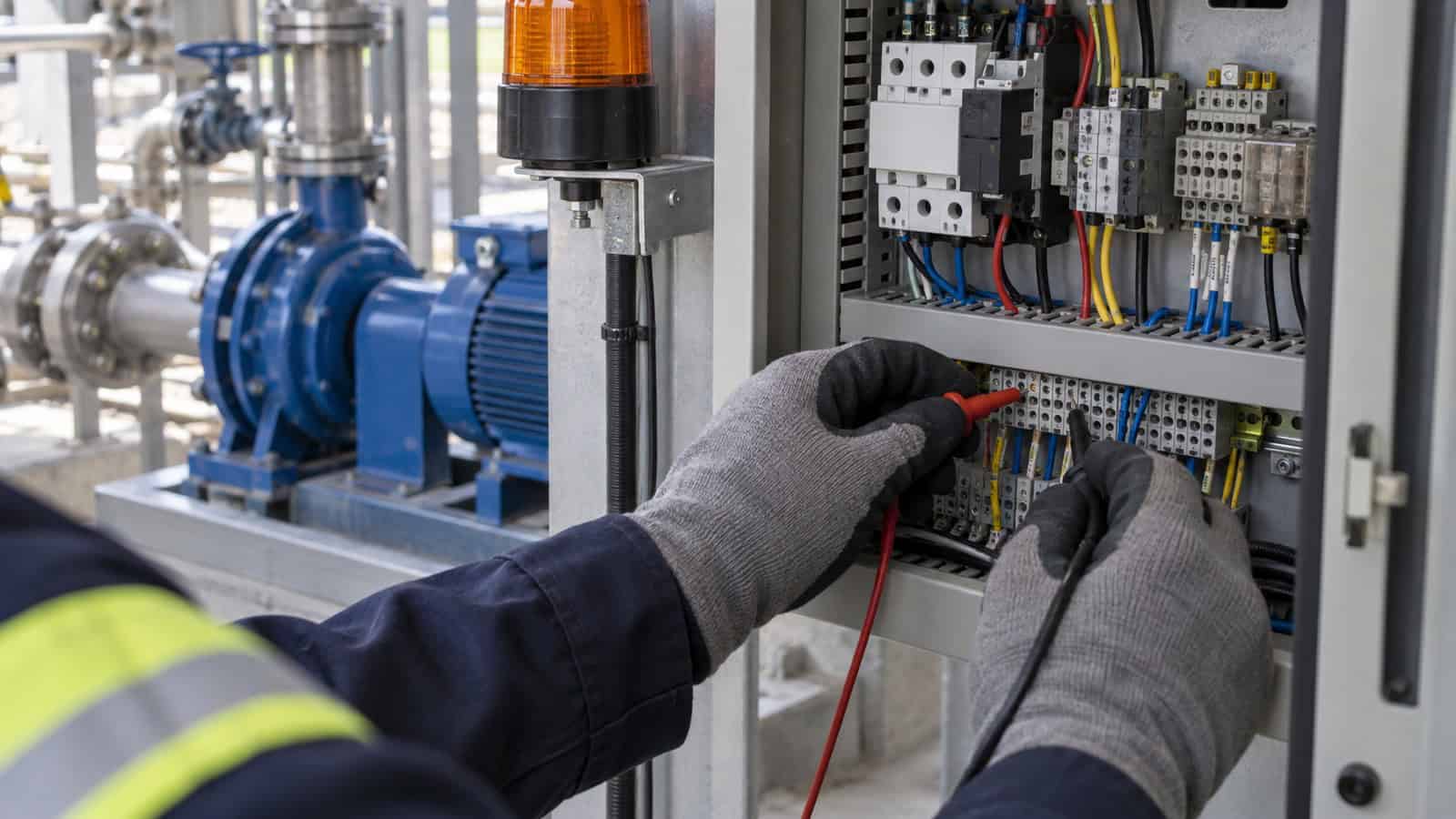
The Robustel EG5200 Edge Computing Gateway provides two wet-contact digital inputs and two dry-contact relay outputs alongside Ethernet, serial, cellular and local compute. That is useful for alarm collection and defined control handoffs, but a relay output is not evidence that the gateway should control a machine or safety function. The electrical circuit, software state and authority of the receiving controller must be designed together.
I start with the unpowered state. If nobody can say what the contact should do when the gateway has no power, the control story is not ready.
Name Every State, Including Unknown
A digital input may represent door open, breaker trip, pump run or a common alarm. Record active voltage, common reference, normal state, debounce, acceptable pulse width and what an open wire looks like. A binary value is only simple after those details are fixed.
For each relay, define normally open and normally closed behaviour, load type, maximum voltage/current and the external circuit it drives. Interposing relays may be required when the field load exceeds the gateway’s documented rating or needs different isolation.
Keep Alarms Separate From Safety
An edge gateway can collect an alarm and notify another system. It should not replace a certified safety relay, emergency-stop circuit or deterministic PLC unless the complete system is designed and approved for that function. Put this boundary on the wiring drawing and in the software requirement.
If a relay requests a reset or mode change, the PLC should retain interlocks and final authority. The gateway’s command should expire, be logged and be rejected when local conditions are unsafe.
Use a State Table Before Writing Logic
| Condition | Input quality | Local indication | Relay behaviour | Upstream record |
|---|---|---|---|---|
| normal | valid | normal | approved resting state | periodic/changed state |
| alarm active | valid | alarm | defined handoff only | immediate event with timestamp |
| input open/invalid | bad or unknown | fault | fail-safe project state | diagnostic event |
| WAN unavailable | valid | local state remains visible | no unapproved change | buffer event for replay |
| gateway rebooting | unavailable | startup indication | documented de-energised state | restart and configuration event |
This table forces the team to distinguish alarm condition from data-quality fault. Without it, a broken wire can be displayed as “everything normal.”
How the Robustel EG5200 Edge Computing Gateway Supports I/O and Relay Handoffs
The Robustel EG5200 Edge Computing Gateway documents two wet-contact digital inputs and two dry-contact relay outputs, plus five Gigabit Ethernet ports and configurable RS-232/422/485. It provides 4 GB RAM, 32 GB eMMC and 4G or 5G variants on RobustOS Pro for local applications.
The relay documentation gives electrical limits and contact terminals; it does not define the project circuit or load. Verify current, voltage, inductive-load protection, isolation, commoning and wiring rules. Use an interposing device where the field circuit requires it.
On the supported EG5200 model, Robustel E2C Factory can link field collection, local logic, buffering, operator views, northbound delivery and controlled outputs through the exact 6C functions: Collect, Compute, Continuity, Canvas, Connect and Control. The practical gain is a clearer relationship between the alarm an operator sees and the field input that created it, with fewer disconnected tools. The project must still define safe states and keep PLC/safety authority intact.
Separate Local Alarm Continuity From Cloud Notification
Decide what happens when the WAN is unavailable. A local lamp, buzzer or relay handoff may continue if it is designed and tested, while cloud notification waits. Buffer the event with its original time and quality. On reconnection, send current state before or alongside the backlog so an old alarm does not obscure a live one.
Robustel’s Public Safety CCTV application example with the EG5100 shows how local site visibility and remote access can support troubleshooting before a field visit is considered. As another model in the Robustel EG Series, it also offers a useful reference for exploring how the product family can support remote monitoring and site-access applications.
Test Faults at the Terminal Block
Software simulation is not enough. Open and short the input as allowed by the design, remove the field supply, cycle gateway power and disconnect the WAN. Verify electrical state, application state, local indication and upstream records each time.
For relays, test a safe representative load and confirm the contact state through boot, application restart and loss of communications. Make sure a queued command cannot execute after its operational context has expired.
Record the fault signature as well as the expected result. A missing field supply, open input wire, failed application and lost WAN may all produce “no alarm” unless separate diagnostics exist. During acceptance, photograph or log the terminal state, gateway input, local application state and upstream event for each injected fault. That evidence gives support staff a way to isolate the physical layer before changing software that was behaving correctly.
Robustel’s Smart Parking application example with the EG5120 shows how cameras, meters, and sensors can be integrated within a wider field architecture, with each device type playing a clear role in the connectivity and data path. As another model in the Robustel EG Series, it also offers a useful reference for exploring how the product family can support mixed-device deployments and remote site operations.
Select the Model From the Electrical Role
EG5100 and EG5120 provide digital inputs and outputs rather than the same relay profile as EG5200. EG3120e offers more numerous wet-contact DI/DO and analogue/CAN interfaces for dense OT collection. Choose the exact signal types and counts first, then compute and network resources.
Robustel RCMS is designed for gateway operations, while the application records alarm state and the PLC or safety system retains its own diagnostic evidence. The EG5000 Series Quick Pitch video can help compare the family at a high level; current datasheets control the I/O design.
Preguntas frecuentes
Q1. What are digital inputs and outputs?
Digital inputs read discrete electrical states, while digital outputs drive defined on/off signals. Their voltage, current, isolation and common reference must match the connected circuit.
Q2. What is the difference between relay output and digital output?
A relay output uses physical contacts and can provide galvanic separation within its rating. A transistor or wet-contact digital output switches electronically and has different wiring and load limits. Check the exact product circuit.
Q3. What are relay outputs?
They are electrically operated contacts that can open or close an external circuit. The relay rating does not guarantee suitability for every load, especially inductive or higher-power equipment.
Q4. What are digital inputs and digital outputs in a PLC?
They are the PLC’s discrete field interfaces for reading switches and sensors and driving actuators or control handoffs. An edge gateway can exchange similar signals but should not automatically take over PLC control authority.
Q5. When is the Robustel EG5200 Edge Computing Gateway a good I/O and relay fit?
It fits when a site needs two digital alarm inputs, two dry-contact relay handoffs, several Ethernet connections and local edge applications in one managed platform. Verify the electrical circuit and safe states before connecting field loads.
Conclusión
The Robustel EG5200 Edge Computing Gateway is a useful choice for local alarm collection and bounded relay handoffs when its documented I/O matches the circuit and the project needs broader edge and network capability. The relay is a controlled interface, not a substitute for the machine’s safety and deterministic control system.
Define unknown and power-off states, keep commands time-bounded, and test faults at the terminal block as well as in software. That discipline produces alarms operators can trust and control handoffs that fail predictably instead of becoming hidden automation.
When an alarm fails in service, start with the field circuit and work inward: voltage and common reference, terminal state, gateway input, application rule, output contact and upstream acknowledgement. A documented sequence is more valuable than a generic “reboot the gateway” instruction because it preserves the evidence needed to distinguish wiring, logic and communications faults.
Explore More Articles About Robustel Edge Computing Gateways




Acerca del autor
Robert Liao | Technical Support Engineer
Robert is an IoT Technical Support Engineer at Robustel, specializing in industrial networking and edge connectivity. A certified Networking Engineer, Robert focuses on the deployment and troubleshooting of large-scale IIoT infrastructures. His work centers on architecting reliable, scalable system performance for complex industrial applications, bridging the gap between field hardware and cloud-side data management.