
How to Add Wireless Monitoring Points to SCADA Without Rewiring the Factory
Connecting LoRaWAN sensors to existing SCADA over Modbus TCP with LG3120e and E2C Field
Factories rarely suffer from a complete lack of data. More often, the problem is that useful information sits just outside the systems operators already use.
A production line may be well instrumented, while electricity consumption in a secondary area is still read manually. A remote workshop may have a water meter but no practical route back to SCADA. A storage area may need temperature and humidity monitoring even though nobody is going to justify pulling new signal cable through an operating facility simply to add two environmental points.
These are not necessarily control problems. They are visibility problems.
That distinction makes LoRaWAN particularly useful in an industrial environment. It provides a way to add low-bandwidth monitoring points in places where extending conventional cabling would be expensive, disruptive or disproportionate to the value of the measurement. The next challenge is bringing those wireless readings into the operational environment without creating another isolated dashboard that operators have to remember to check.
With the Robustel LG3120e and E2C Field, supported LoRaWAN sensor data can be received and decoded locally, converted into usable Tags, mapped to Modbus registers and exposed to the existing SCADA system over Modbus TCP. Operators can continue working with familiar screens, trends and alarm workflows rather than treating wireless sensing as a separate monitoring island.
The radio link is only the beginning of that integration. The more important work is agreeing exactly what each measurement means once it reaches SCADA.
Keep the existing SCADA at the centre
In this architecture, the LG3120e receives the LoRaWAN reports while E2C Field’s embedded network server and payload codecs turn supported device payloads into usable Tags. Those Tags are then mapped to Modbus registers, which the existing SCADA reads as a Modbus TCP client.
E2C Field provides the Modbus server function, labelled Modbus TCP Slave in the current interface.
The objective is not to replace SCADA or move factory control into a wireless application. Existing machine control, safety interlocks and other deterministic functions should remain on the dedicated systems designed for them.
The LoRaWAN path is better suited to periodic utility and environmental monitoring: measurements that improve operational visibility without becoming part of a time-critical control loop.
A useful first project might therefore be deliberately modest: one utility meter and one environmental sensor. That is enough to prove the complete path from wireless acquisition through decoding and register mapping to the operator screen before the same pattern is extended to additional areas.

Figure 1. LoRaWAN can extend monitoring into hard-to-wire areas while Modbus TCP presents the measurements to the existing SCADA. PLC, DCS and safety systems remain unchanged.
Start with a factory question, not a sensor catalogue
The most useful deployments begin with something operations actually wants to understand.
Perhaps the question is why electricity consumption remains high after the last production shift. Perhaps it is whether a remote workshop is consuming more water than expected, or whether temperature and humidity in a storage area remain within acceptable conditions.
The sensor follows the question.
For example, the Adeunis PULSE can provide a sensing path for pulse-enabled utility meters, while the Netvox R718A provides temperature and humidity monitoring. Both appear in Robustel’s supported-device overview, although the exact hardware variant, regional radio band, firmware and codec should always be confirmed before procurement and commissioning.
For pulse-based metering, the physical meter specification remains important. A pulse count has no useful engineering meaning until the project applies the meter’s documented pulse constant.
If, for example, an electricity meter is configured so that 1,000 pulses represent 1 kWh, an increase of 2,500 pulses represents 2.5 kWh. A water meter will use its own volume-per-pulse relationship.
The integration also needs to establish whether the decoded value represents a cumulative counter or an interval count, and how counter resets or rollover should be handled. The 1,000-pulse figure above is illustrative and project-specific rather than an Adeunis default.
This is a useful reminder that the gateway can transport and expose the measurement, but the engineering meaning still comes from the device and the application.
Prove the decoded value before involving SCADA
Before building the Modbus map, complete the LoRaWAN onboarding process and confirm that the sensor data is correct in E2C Field.
In Data Collection, inspect a genuine uplink and check the decoded Tags, including the value, engineering units and update time. The purpose is to establish a trustworthy source before introducing another layer of mapping.
If the sensor says 23.4 °C, E2C Field should show the expected 23.4 °C value with the correct meaning and units before the SCADA engineer is asked to consume it.
This sounds obvious, but it prevents a common integration problem: trying to debug the sensor, payload decoder, Modbus mapping and SCADA driver simultaneously. Proving each layer in sequence makes faults much easier to isolate.
Treat the register map as the contract between LoRaWAN and SCADA
Once the source Tags are trusted, the SCADA team needs a clear definition of how those values will appear over Modbus.
That definition is the register map.
Upstream of the map sits the wireless world: sensor identity, LoRaWAN payload, codec, Tag name, value and engineering units.
Downstream sits the SCADA world: function code, register address, register count, data type, byte order, point name and operator display.
The register map is where those two worlds agree.
The worked example uses read-only input registers and Function Code 04 (FC04). Each value occupies two 16-bit registers. A UInt32 pulse counter is made available for consumption calculations in SCADA, while Float32 temperature and humidity values are presented directly in engineering units.
An illustrative mapping might look like this:
| SCADA point | Example type | Registers | Purpose |
|---|---|---|---|
meter_pulse_total | UInt32 | 2 × 16-bit | Cumulative pulse count for utility calculation |
zone_temperature | Float32 | 2 × 16-bit | Temperature in engineering units |
zone_humidity | Float32 | 2 × 16-bit | Relative humidity in engineering units |
These names and addresses are examples, not vendor defaults. The actual point aliases, addresses, function codes and data types should be agreed between the commissioning team and SCADA integrator for the specific project.
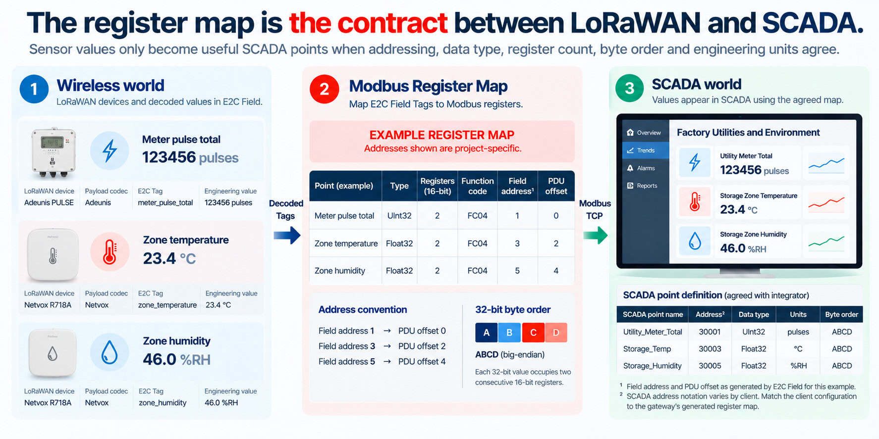
Figure 2. An example register map translates decoded LoRaWAN measurements into the addressing, data types, register counts and engineering units expected by SCADA. Addresses shown are project-specific.
Modbus addressing is simple until two systems describe it differently
In E2C Field, the Modbus TCP service is created under Data Forwarding. The project defines the port, Slave Address and mapping table, then associates each source Tag with its mapped value, data type, function code and address.
Where the value has already been converted into the required engineering units, Data Operation Value can be used. Data Original Value retains the original reading.
The important principle is to apply a conversion once, rather than accidentally applying the same scaling in both the gateway and SCADA.
The SCADA client then connects to the gateway’s local IP address. In the worked example, the connection uses:
- Unit ID: 1
- Port: 502
- Function: FC04
- Six registers: three consecutive two-register values
These are example settings rather than universal defaults.
Particular attention is required around addressing conventions. The example uses field initial addresses 1, 3 and 5, corresponding to zero-based Modbus Protocol Data Unit offsets 0, 2 and 4. Some SCADA clients may display those same locations using references such as 30001.
The driver configuration therefore needs to be matched to the address convention shown by the gateway’s generated mapping rather than relying on assumptions about how a particular client labels registers.
This is one of those details that can consume far more commissioning time than its apparent complexity deserves. Both devices may be functioning perfectly while the engineer is simply reading the wrong location.
Data type and byte order can produce believable errors
Addressing is not the only place a Modbus integration can go wrong.
The worked example represents each 32-bit value across two consecutive 16-bit registers, with ABCD byte order matching the read-only default described in the current E2C Field documentation.
Where a SCADA driver exposes word-swap or byte-swap options, the resulting sequence should be verified against a known source value.
That test is worth doing because an incorrectly assembled 32-bit value does not always look obviously broken. Depending on the data, it can produce a number that appears plausible enough to escape immediate attention.
Comparing the SCADA value directly with the proven source Tag removes the ambiguity.
Once the values agree, bind the points into the factory’s normal operator environment: clearly named screens, trends, historian tags and alarms where appropriate. Engineering units and alarm thresholds should be agreed with operations rather than inferred during integration, and the Modbus service should remain on a controlled OT network accessible only to authorised clients.
A successful Modbus read does not prove the sensor data is fresh
This is one of the most important distinctions in the whole integration.
Suppose the LoRaWAN temperature sensor normally reports every five minutes and the SCADA polls the gateway every five seconds.
The SCADA connection may succeed every five seconds, but that does not mean a new temperature measurement exists every five seconds. Until the next sensor report arrives, the gateway will continue returning the latest available value.
A flat trend might therefore mean the temperature genuinely remained stable, or it might mean the sensor has stopped reporting entirely. The Modbus connection can remain healthy in both cases.
The solution is to treat source-data freshness separately from Modbus communication status.
A project can use verified update metadata, an uplink counter or appropriate application logic to create a freshness indication where one is required. This is additional project configuration rather than a built-in register supplied by the example.
A stale-data threshold should also reflect the actual reporting interval and expected radio behaviour. If the sensor normally reports every five minutes, missing one expected update is different from losing data for an hour.
The operator ultimately needs to distinguish between conditions such as:
| Condition | Modbus connection | Sensor data |
|---|---|---|
| Normal operation | Healthy | Updating normally |
| Sensor has stopped reporting | Healthy | Stale |
| SCADA cannot reach gateway | Failed | Unknown to SCADA |
That separation makes maintenance substantially easier. If SCADA is still reading the gateway successfully but the timestamp for one sensor has stopped advancing, the investigation should move toward the wireless device or radio path rather than the Modbus network.
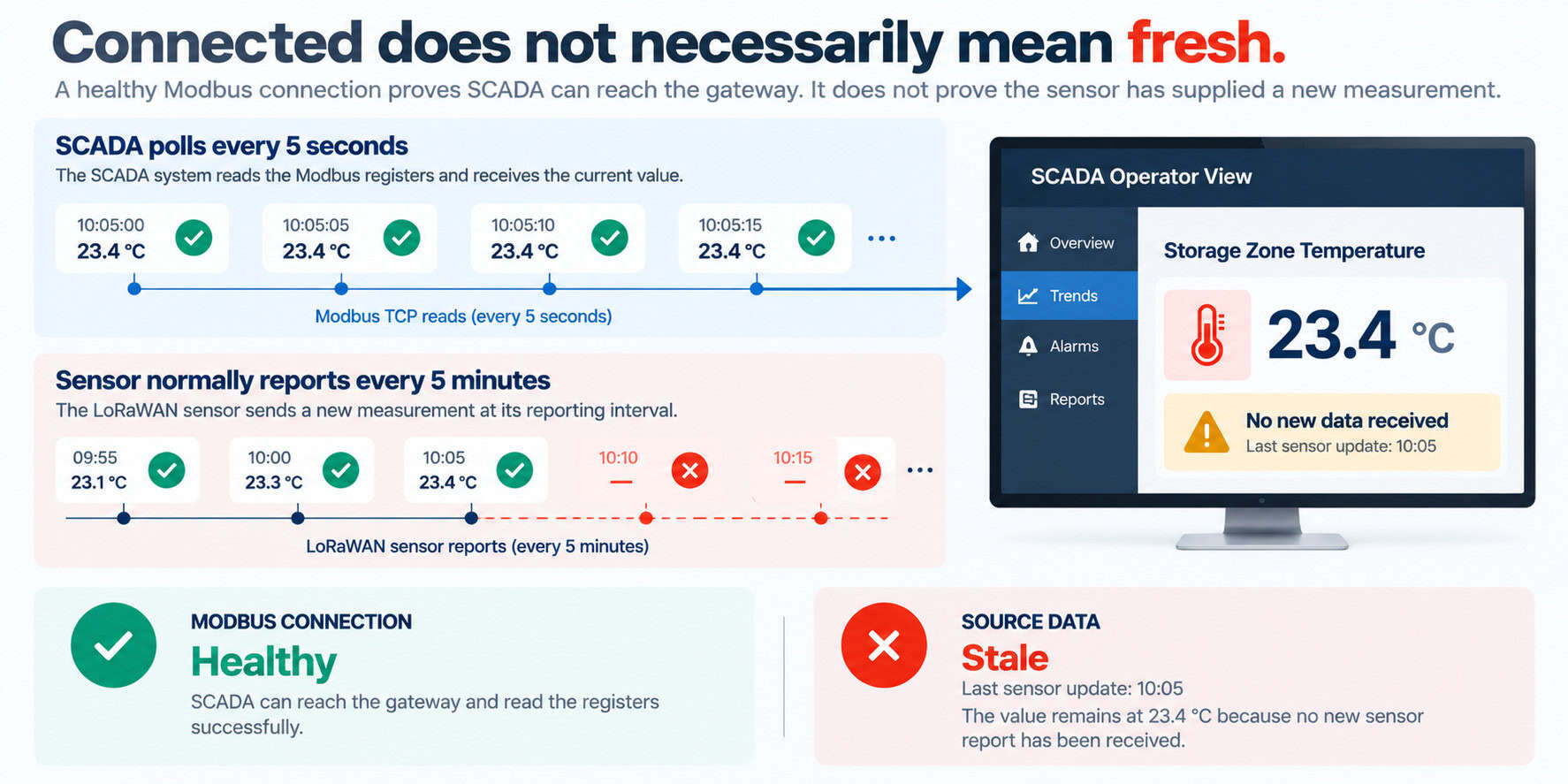
Figure 3. A healthy Modbus connection proves that SCADA can reach the gateway. It does not prove that the LoRaWAN sensor has supplied a new measurement.
Prove the whole path with a small factory pilot
A pilot should demonstrate more than the fact that registers can be read.
Start by comparing each source Tag in E2C Field with the corresponding SCADA point, including sign, decimals and engineering units. Then wait for a genuine new sensor report and verify that the update appears correctly at both ends.
For pulse metering, introduce or observe a known pulse increment and reconcile the counter change with the resulting utility calculation. Any test should avoid disturbing production or billing equipment.
The pilot should also test failure behaviour:
- Confirm the normal data path. Verify the sensor value, E2C Field Tag and SCADA point agree.
- Wait for a genuine source update. Confirm that SCADA receives the new value rather than simply continuing to read the previous register contents.
- Test a missed sensor report. Verify that the project’s stale-data indication behaves as expected.
- Interrupt the SCADA network path. Confirm that the communication alarm is clearly different from a stale wireless measurement.
- Restore each condition and verify recovery. Make sure both the source and communication status return to normal.
If a value differs from its source Tag, work through the integration systematically: address base, function code, register count, data type and byte order.
Once one utility point and one environmental point have been validated this way, the project has more than a successful proof of concept. It has a repeatable integration pattern.
Local SCADA does not have to depend on the internet
There is another architectural advantage to keeping the acquisition and Modbus path local.
An internet outage does not necessarily need to interrupt the factory’s local monitoring. If gateway power, sensor radio links, the LAN and the required local services remain available, LG3120e and E2C Field can continue collecting LoRaWAN measurements and serving current values to local SCADA over Modbus TCP.
Where the same project also forwards information to a remote platform, configured MQTT reports can be buffered within the available cache capacity and retention period and delivered when the upstream service returns.
That cloud-recovery path is separate from the normal Modbus reads used by local SCADA and does not automatically backfill SCADA history.
This distinction is worth making because “edge” can otherwise become a vague marketing term. In this case, its value is concrete: wireless acquisition, payload decoding and SCADA integration can remain inside the factory network rather than depending on a remote service for every useful function.
Extend visibility without redesigning control
The most useful role for LoRaWAN in this architecture is not replacing what already works.
SCADA remains the operational environment. Existing control systems remain responsible for machine behaviour and safety. LoRaWAN simply extends the measurement layer into places that may have been difficult or uneconomic to instrument using traditional wiring.
That can include utility consumption, environmental conditions and other periodic monitoring points that improve the factory’s operational picture without needing to become part of a deterministic control loop.
With LG3120e and E2C Field, Robustel provides the local LoRaWAN network, payload processing and Modbus TCP integration needed to bring those measurements into the existing OT environment. The technical success of the project, however, still depends on getting the fundamentals right: validate the sensor data, agree the register contract, verify data types and addressing, make freshness visible, and prove the complete path before expanding the deployment.
Once that pattern is established, adding another wireless monitoring point no longer has to mean designing another isolated system.
It becomes another source of useful data inside the SCADA environment the factory already understands.
Planning to extend factory monitoring without adding new signal cabling?
Start with the measurements operations actually needs, the locations that are difficult to instrument today, and the way those values should appear inside the existing SCADA environment.
Robustel or your integration partner can help assess compatible LoRaWAN devices, define the E2C Field integration and validate the Modbus TCP mapping for an LG3120e + E2C Field pilot.