
From LoRaWAN Sensor to BACnet BMS: A Practical LG3120e + E2C Field Walkthrough
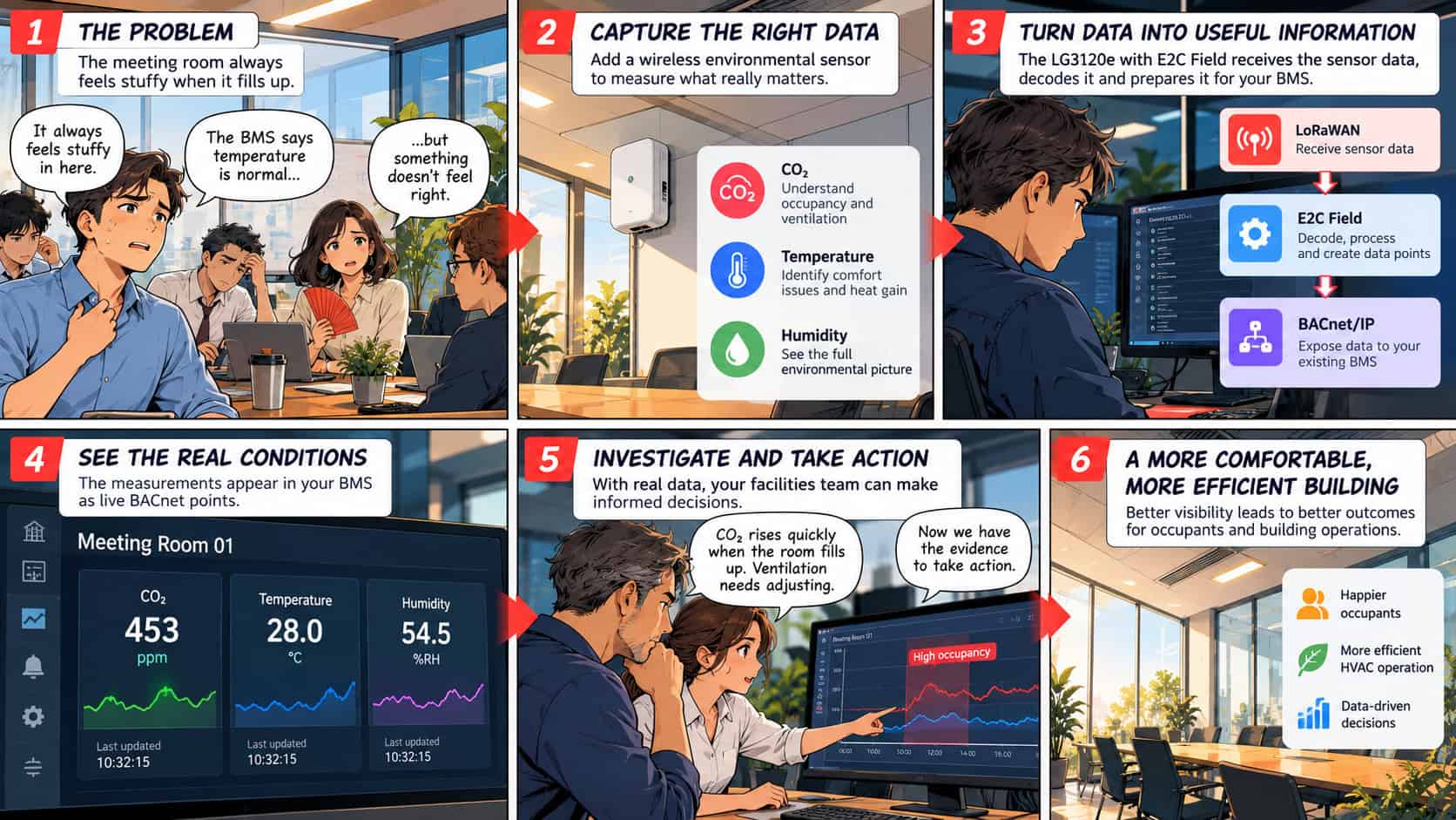
A meeting room feels stuffy whenever it fills up.
The BMS says the temperature is normal.
So what is actually happening?
Adding a wireless environmental sensor can give the facilities team the missing evidence — CO₂, temperature and humidity from the room itself.
But collecting the measurement is only the beginning.
The real integration work is turning a LoRaWAN message into data the existing BMS can understand, trust and use.
In this walkthrough, we use a Milesight AM103, Robustel LG3120e and E2C Field to follow that complete path:
LoRaWAN sensor → decoded measurement → E2C Tag → BACnet/IP object → existing BMS
The objective is not simply to get one sensor online.
It is to prove a sensor-to-BMS integration that can be repeated when one room becomes ten, one floor becomes a building, or a successful proof of concept becomes a wider deployment.
Start with the question, not the sensor
IoT projects often begin with a device.
A more useful place to begin is with the question somebody wants answered.
In this example:
Why does this meeting room become uncomfortable when it is full?
That immediately gives the measurements a purpose.
CO₂ can help show how conditions change as the room fills and empties.
Temperature and relative humidity provide additional environmental context.
If occupancy or HVAC information is already available in the BMS, the new measurements can then be compared with what the building was doing at the same time.
The goal is to move from:
“This room feels stuffy.”
to something more useful:
“CO₂ consistently rises when this room is heavily occupied. We now have a specific operating period worth investigating.”
The sensor does not make the decision.
It gives the building team better evidence to make one.
What has to happen between the sensor and the BMS?
Getting a LoRaWAN packet from a sensor to a gateway solves the connectivity problem.
It does not yet solve the integration problem. Between the wireless message and the point an operator eventually sees in the BMS, several things have to happen:
Sensor → LoRaWAN Network Server → Payload Codec → E2C Tag → BACnet Object → BMS
Each stage has a different job.
- The LoRaWAN network receives the sensor message.
- The payload codec determines what the encoded message actually means.
- E2C Field turns those decoded measurements into usable Tags.
- The BACnet/IP Server exposes selected Tags to the existing BMS.
That distinction is important.
The LG3120e + E2C Field combination is valuable here because the gateway is doing more than forwarding LoRaWAN packets somewhere else.
It becomes the local integration point between the field devices and the operational system that needs the data.
Before you begin
For this example, prepare:
- A Robustel LG3120e with E2C Field
- A suitable LoRaWAN antenna
- Access to the intended BACnet/IP network
- A Milesight AM103
- The actual LoRaWAN provisioning information for that sensor
- The required BMS point names and acceptance criteria
This walkthrough uses the AM103 as the worked example because it provides three useful room measurements:
- CO₂
- Temperature
- Relative humidity
Confirm the actual radio region, MAC version, regional parameters, device firmware and reporting configuration on the sensor being deployed.
This example assumes EU868 and OTAA, but the project configuration should always match the actual hardware and deployment region.
Read the real:
- DevEUI
- AppEUI or JoinEUI
- AppKey
from the device provisioning information or Milesight ToolBox.
Do not assume default credentials, and do not include real device keys in screenshots, example workbooks or public documentation.
The AM103 manufacturer default application port is FPort 85, but the installed device configuration should still be confirmed before commissioning.
Step 1: Make sure the gateway understands what the sensor is telling you
Receiving the radio message is not enough.
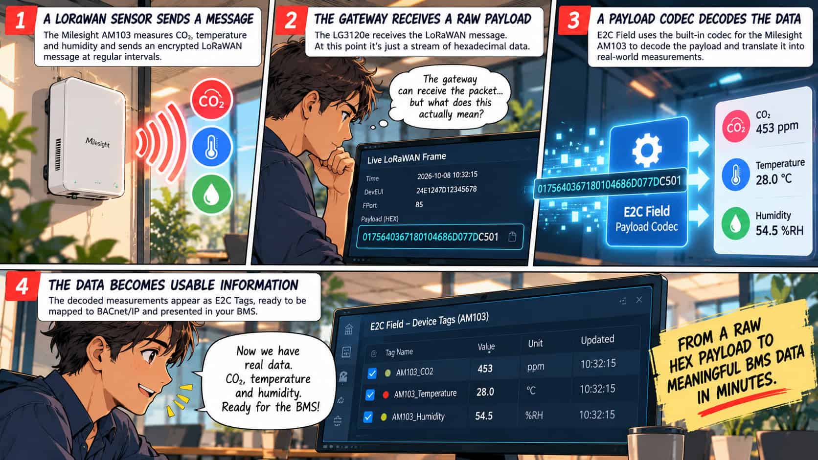
A raw LoRaWAN payload might look like this:
0175640367180104686D077DC501
That string is meaningful to software.
It is not meaningful to a building operator.
With the correct payload decoder, the same message becomes:
Temperature: 28 °C
Relative humidity: 54.5%
CO₂: 453 ppm
That transformation is one of the most important steps in the integration.
Check the LoRaWAN service
In E2C Field, open:
LNS Configuration → Service Information
Confirm that the service is running and that the configured region matches the gateway, sensor and deployment.
Next open:
LNS Configuration → Payload Codecs
Find the exact sensor model and confirm that the published codec matches the sensor firmware and payload format.
It should also expose the measurements the project actually requires.
A sensor appearing in a support catalogue does not remove the need to verify the installed sensor, firmware and codec combination.
Check the device profile
Open:
LNS Configuration → Device Profiles
Select a matching profile or create one where required.
The profile should reflect the actual device configuration, including:
- 地域
- Channel plan
- MAC version
- Regional parameters revision
- Activation method
- Device class
- Expected uplink interval
Associate the verified payload codec with the profile and publish it.
Keep the published profile name exactly as configured.
That name will be used later during Z-touch onboarding.
What if the sensor is not already supported?
There are three practical routes.
Use existing built-in support
If the exact sensor model and required payload format are already supported, use the validated codec and matching published device profile.
This is the simplest path.
Convert and import a supported decoder
Where an appropriate manufacturer decoder exists in a supported format, Robustel provides a codec conversion and import workflow.
For supported Milesight source files, the required decoder folder structure should be preserved when using the E2C Trinity Codec Converter.
After conversion, import the generated codec into:
Payload Codecs → Import Codec → Import from file
Then use Uplink Test → Run Decode with a known model-specific payload.
Verify the fields and values before publishing the codec.
Ask Robustel engineering to help add support
If the exact model is unavailable or conversion is not appropriate, the sensor documentation, decoder information and representative payloads can be provided to Robustel engineering for assessment.
Whichever path is used, the goal is the same:
A validated payload codec + a matching published device profile
Only then should the device move into repeatable onboarding.
Step 2: Avoid configuring every sensor by hand
One sensor is easy to configure manually.
Fifty sensors are less attractive.
Five hundred make repetitive commissioning a serious part of the project.
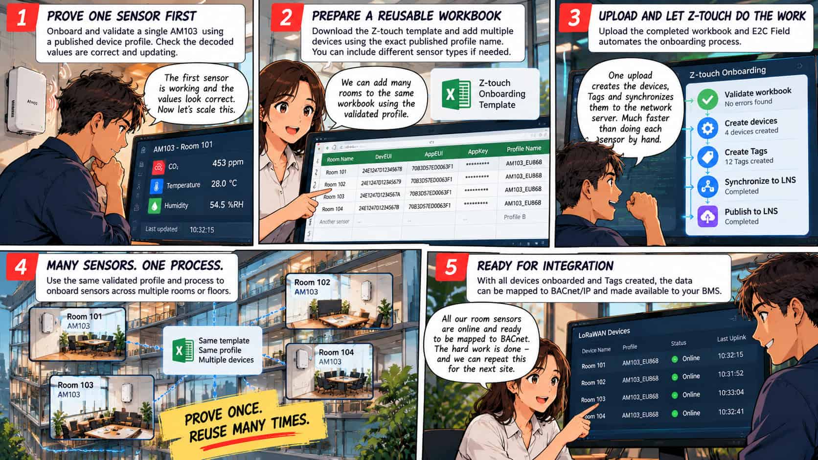
Once the codec and device profile have been validated, Z-touch onboarding provides a way to reuse that work.
Open:
Z-touch Onboarding → Onboarding → Download Template
Use the downloaded XLSX template and its field comments rather than recreating the workbook structure manually.
Enter the real provisioning data for each sensor.
The Profile name must exactly match the published profile, including capitalization.
The workbook can contain multiple devices and, where required, multiple published profiles.
For the first proof of concept, however, keep the scope controlled.
Validate the AM103 first.
Once that profile and codec combination is proven, reuse it.
What happens when the workbook is uploaded?
Upload the completed workbook and continue to validation.
Any row errors, profile mismatches or capacity issues should be corrected before execution.
Once validation succeeds, Z-touch automates the onboarding sequence:
Validate workbook → Create devices → Create Tags → Synchronize to LNS → Publish to LNS
That workflow matters because it changes what happens when a successful pilot grows.
Instead of rebuilding each sensor manually, the validated profile becomes part of a repeatable onboarding process.
During the onboarding operation, keep the page open, avoid refreshing it and avoid concurrent LoRaWAN device edits or publication operations.
Successful Z-touch onboarding creates the devices and Tags and synchronizes them with the LoRaWAN Network Server.
BACnet mapping remains a separate step.
First prove the sensor data, Then integrate it into the BMS.
Step 3: Prove the number means what you think it means
A device showing as Online is not the end of commissioning.
Now verify what it is actually reporting.
Power on or trigger the AM103 according to the manufacturer instructions.
In E2C Field, open:
Data Collection → LoRaWAN Devices
Confirm the device is online.
Then open:
View Tags
Check the latest decoded values.
Wait for another genuine sensor report and confirm that the Update Time advances. This matters because a plausible value is not enough.
You need to know that the data is current.
If uplinks are arriving but the Tags are empty or incorrect, open:
LNS Configuration → Live Frames
Compare the raw message with the decoded result and confirm the correct codec is assigned.
Verify the meaning, not just the name
The Milesight decoder may expose fields such as:
temperaturehumidityco2
The E2C Tags created on the gateway may use different names.
Do not assume two fields represent the same thing simply because their names look similar.
Verify:
- Measurement meaning
- Data type
- Engineering units
- Scaling
- Latest value
- Update time
The integration chain should make sense before the data reaches BACnet.
For the documented AM103 example payload:
0175640367180104686D077DC501
the manufacturer decoder produces:
Temperature: 28 °C
Relative humidity: 54.5%
CO₂: 453 ppm
Battery: 100%
These are example manufacturer values. A real deployment should be commissioned against genuine sensor uplinks from the actual installed device.
Step 4: Turn the measurements into something the BMS can actually use
At this point:
- The AM103 is online
- The payload codec is working
- The decoded measurements have been verified
- E2C Field has created usable Tags
Now those measurements can be exposed to the building system.
Open:
Data Forwarding → Create
Select:
BACnet IP Server
Save the service and open its configuration.
Configure the required:
- Local network interface
- UDP port
- Unique Local Device ID
- Original or processed value behaviour
The BMS must be able to reach the configured interface.
BBMD and BDT configuration should only be used where the BACnet network design requires broadcast forwarding between network segments.
Map the E2C Tags to BACnet objects
Open the:
BACnet IP Mapping Table
Add each required measurement.
Select the relevant device and verified source Tag.
For the read-only numeric measurements in this example, use:
AI — Analog Input
Assign each object a unique instance.
A conceptual mapping could look like:
Meeting Room 01 Temperature → AI-101
Meeting Room 01 Humidity → AI-102
Meeting Room 01 CO₂ → AI-103
The actual object numbering and naming convention should follow the customer’s BMS standards.
Record the:
- Room
- Measurement
- Source device
- Source Tag
- BACnet object type
- BACnet instance
- Engineering units
in the commissioning documentation.
Save the mapping and apply the configuration using the controls available in the installed E2C Field release.
Open Status and confirm that the BACnet/IP service has started.
Discover the point from the BMS
Using the target BMS or a commissioning client such as Yabe, discover the gateway using its BACnet Device ID.
Read the mapped Present_Value.
Compare it directly with the E2C Tag verified in the previous step.
If E2C Field shows: CO₂: 453 ppm
then the mapped BACnet object should represent the same measurement correctly.
Now wait for the next genuine sensor report.
The BACnet value should update too.
That is the point where the complete integration begins to prove itself.
Step 5: Prove the complete path before you scale it
A successful import proves that the device configuration exists.
Commissioning proves that the building team can trust the result.
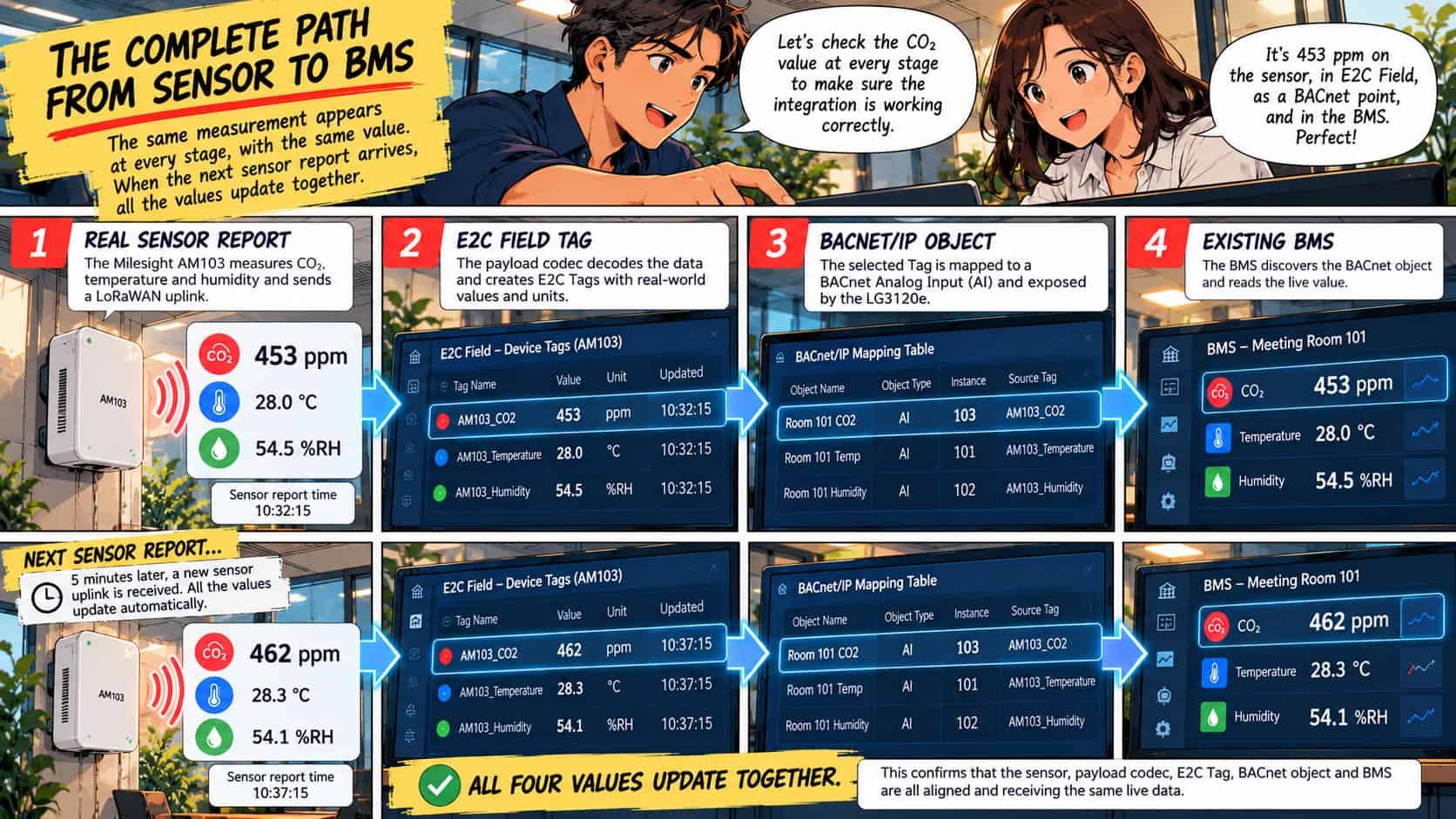
Choose one measurement and follow it through the entire chain.
For example:
Real AM103 sensor report
CO₂ = 453 ppm
↓
E2C Field Tag
CO₂ = 453 ppm
↓
BACnet AI-103
Present_Value = 453
↓
Existing BMS
Meeting Room 01 CO₂ = 453 ppm
Every stage should represent the same measurement, from the same device, using the agreed units and value path.
Then wait for the next genuine report.
If the next sensor message reports:
CO₂ = 462 ppm
the same change should propagate through:
Sensor → E2C Tag → BACnet object → BMS
That second update is important.
It proves that you are seeing live operational data rather than simply comparing stored values.
Commission the data, not just the connection
Before considering the integration complete, check more than whether the BACnet object exists.
Correct measurement
Confirm that:
- CO₂ is represented in ppm
- Temperature uses the agreed scale
- Humidity represents relative humidity
- Scaling or conversion has not accidentally been applied twice
Fresh data
Confirm that a subsequent real sensor report refreshes the E2C Tag and reaches the mapped BACnet object. Judge freshness against the configured reporting interval.
Clear identification
The BMS point name, room assignment and source device should agree. Record the BACnet object instances and units in the commissioning documentation.
Loss and recovery
During an approved test window, check what happens when uplinks stop and when the sensor reconnects. A stale but believable value can be misleading if an operator assumes it is current. Agree how stale data should be identified or handled.
Useful operation
Finally, make the measurement useful.
Add the required:
- BMS graphics
- Trends
- Alarms
- Operator labels
Z-touch can automate device and Tag creation.
It does not decide how the building team should use the resulting information.
That is a commissioning decision.
The first sensor proves the integration. The next sensors prove the deployment model.
Once the first AM103 has been commissioned successfully, the project has achieved far more than establishing LoRaWAN connectivity.
You now have a validated chain:
Sensor firmware → payload codec → published profile → Z-touch onboarding → E2C Tags → BACnet mapping → BMS commissioning
Keep a controlled record of that configuration.
For the next room, the device identity and point names will change.
The integration method does not need to be reinvented.
For a new sensor type, validate the support once and then bring it into the same onboarding and commissioning process.
That is where the real value of a repeatable integration starts to appear.
A proof of concept should make the next deployment easier
A proof of concept with one manually configured sensor can demonstrate that a technology works. It may not demonstrate that the technology is practical to scale.
A stronger proof of concept answers two questions:
Does this measurement help solve the customer’s problem?
and:
Can we deploy the same integration again without starting from scratch?
That is why the sensor profile, codec, onboarding workflow and BACnet mapping matter.
The first deployment establishes the pattern; The next deployment reuses it.
As the project grows from:
one sensor → one room → one floor → one building → multiple sites
the value moves beyond simply getting packets from A to B. It becomes the ability to turn field-device data into trusted operational information repeatedly.
Start with the question your building needs answered
The worked example in this article begins with a meeting room, your project may start somewhere completely different:
- Maybe one area is consistently uncomfortable.
- Maybe you need additional environmental monitoring.
- Maybe you want to investigate ventilation performance.
- Maybe the building team needs a new measurement before changing an operating schedule.
The process remains fundamentally the same:
- Start with the operational question.
- Choose the measurement that can help answer it.
- Validate the sensor and codec.
- Turn the measurement into a usable E2C Tag.
- Expose it through BACnet/IP.
- Prove the complete path using real data.
- Then reuse the validated integration.
That is where the LG3120e + E2C Field combination goes beyond simply connecting another LoRaWAN sensor.
It provides the integration layer between what is happening in the physical environment and the systems the building team already uses to operate it.
Ready to prove a LoRaWAN-to-BMS use case?
Bring the sensor model, the measurement you need and the BMS interface requirements.
Robustel or your integration partner can help assess the device support, gateway configuration and integration path for an LG3120e + E2C Field proof of concept.